The autotrace program accepts bitmap graphics from the file inputfile specified on the command line, and as output produces a collection of splines approximating the original image, the converting the image from bitmap to vector format. It behaves in a manner similar to the commercial software known as *tream*ine or *orel*race. The result is sent to standard output unless the -output-file option is active.
We are using Inkscape to apply a path tracing filter to called Centerline tracing, or autotrace, to an “automatic drawing” made in pen in 1946 by Asger Jorn. The drawing would serve as the basis for a series of works made by Jorn and invited others to find new novel forms among the randomly made lines by removing “superflous material” to reveal an underlying image. Autotrace is a free software project initiated by Martin Weber that according to the man(ual) page, compares itself to commerically implemented algorithms like Adobe’s Streamline and Corel Trace (though removing key letters to avoid direct citation).
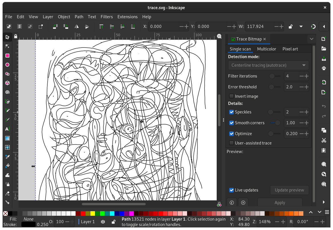
The result is a single large SVG path object. (contains m, c, and l)
 <path
       style="fill:none;stroke:#000001;stroke-width:0.25;stroke-miterlimit:4;stroke-dasharray:none;stroke-opacity:1"
       d="m 43.195497,12.958371 c 0.629857,-0.39497 1.180148,-0.731964 1.8415,-1.111694 0.305372,-0.175324 0.529781,-0.294958 0.889,-0.448691 0.412052,-0.17634 0.789813,-0.328422 1.2065,-0.549085 0.183515,-0.09716 0.320358,-0.174879 0.508,-0.263525 0.647573,-0.305924 1.306132,-0.55579 1.9685,-0.8381107 0.400812,-0.170827 0.854456,-0.2935157 1.27,-0.3871207 0.335344,-0.07553 0.704279,-0.20461 1.0795,-0.288404
...
According to the SVG specification, a path definition is a sequence of coordinates and commands that instruct a virtual pen to trace the forms of a shape.
he “Move to” command is called with the letter
M. When the parser runs into this letter, it knows it needs to move to a point. So, to move to (10,10) the command to use would beM 10 10. After that, the parser begins reading for the next command.All of the commands also come in two variants. An uppercase letter specifies absolute coordinates on the page, and a lowercase letter specifies relative coordinates (e.g., move 10px up and 7px to the left from the last point).
…
There are five line commands for
<path>nodes. The first command is the “Move To” orM, which was described above. It takes two parameters, a coordinate (x) and coordinate (y) to move to. If the cursor was already somewhere on the page, no line is drawn to connect the two positions. The “Move To” command appears at the beginning of paths to specify where the drawing should start.There are three commands that draw lines. The most generic is the “Line To” command, called with
L.Ltakes two parameters—x and y coordinates—and draws a line from the current position to a new position.…
The cubic curve,
From https://developer.mozilla.org/en-US/docs/Web/SVG/Tutorial/PathsC, is the slightly more complex curve. Cubic Béziers take in two control points for each point. Therefore, to create a cubic Bézier, three sets of coordinates need to be specified.
C x1 y1, x2 y2, x y
(or)
c dx1 dy1, dx2 dy2, dx dy